Rotary Encoders: Magnetic Vs Optical Principles
Magnetic Measurement Principles

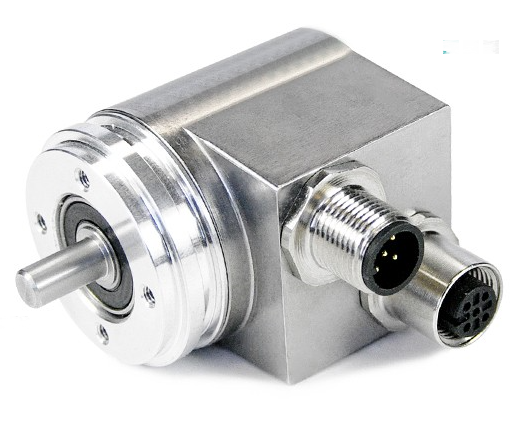
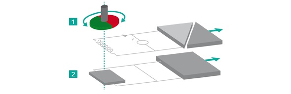
Magnetic rotary encoders determine angular position using magnetic field sensor technology. A permanent magnet (1) is fixed to the encoders’ shaft and creates a magnetic field that is in turn sampled by a sensor (2) that generates a unique absolute position measurement.
Signal Processing Results In High Performance
POSITAL’s IXARC magnetic encoders can perform at the performance level of optical systems due to a new generation of sensor systems. The combination of a custom Hall-effect sensor and complex signal processing algorithms running on a powerful 32 bit microprocessor, results in a significantly improved resolution and accuracy, along with a minimal latency only a few microseconds.
Multiturn Measurement Technology
Multiturn measurements are achieved by means of a revolution counter system that uses an energy harvesting system based on the Wiegand effect. This system requires no gears or batteries. Eliminating batteries brings about many advantages over traditional multiturn solutions. Batteries have a limited lifespan, weigh a lot, and often contain harmful substances. Gear units also have disadvantages of their own being large, complex, costly and vulnerable to shock and vibration. Regardless of the rotational speed, even at near-zero, the energy harvesting system generates short, powerful voltage pulses, sufficient to power the counting electronics. The result is a revolution counter that is independent of any external power supply. This technology, which has been proven for over 12 years enables maintenance-free reliable measurement of absolute positions, even in demanding environments.
Advantages of Magnetic Encoders
- Robust and durable
- Mechanically simple and economical − no battery, no gear
- Compact design for installation in small spaces
Rotary Encoders: Magnetic Vs Optical Principles
Optical Measurement Principles

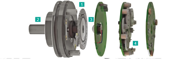
A key component of optical rotary encoders is a code disk (1) which is mounted on the encoder shaft (2) . This disk is made of high durability plastic that has a concentric pattern of transparent and opaque areas. Infrared light from an LED (3) shines through the code disk, onto an array of photoreceptors. As the shaft turns, a unique combination of photoreceptors are illuminated or blocked from light by the pattern on the disk. For multiturn models, there is an additional set of code discs arranged in a gear train (4) . As the main encoder shaft rotates, these discs are geared together to turn like the wheels of an odometer. The rotational position of each disc is monitored optically and the output is a count of the net number of rotations of the encoder shaft.
Functionality
POSITAL’s IXARC optical absolute rotary encoders use highly integrated Opto-ASICs, providing a resolution up to 16 bits (65,536 steps) per turn. For multiturn models, the measuring range is extended by the mechanically geared code disks to as many as 16,384 revolutions.
Advantages of Optical Encoders
- High resolution and accuracy along with excellent dynamic response
- For use in areas with high magnetic fields
- No risk of these devices losing track of their absolute position
- No backup batteries required